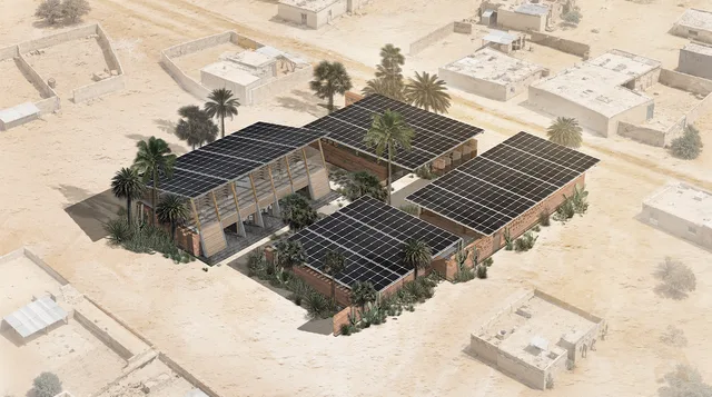
OVERVIEW
ARCHITECTURE / 04M / SELECTED PROJECT
THE NEXUS NODE
Rochdale, UK | 2024-2025 | Individual Work | Academic Study
+ Modelling:

+ Visualisation:
+ Post-production:

An Incubator for Future Design and Manufacturing
The Nexus Node is an adaptive reuse project located at Kingsway Business Park in Rochdale. It proposes an integrated circuit design incubator that supports Atom Valley’s future development and strengthens the advanced manufacturing network in Greater Manchester.
The project provides flexible office units, shared workshops, advanced laboratories, testing spaces, mentorship areas, and networking facilities for start-ups and research teams. By combining technical infrastructure with collaborative social spaces, the building helps young companies develop skills, access support, and grow within a shared innovation environment.
Using the idea of an incubator as both a business model and a spatial concept, the project creates a place where ideas can be tested, supported, and developed into successful outcomes. It aims to attract talent, support regional economic growth, and create a sustainable platform for future technology and design industries.
01
OVERVIEW
12 WORKSOVERVIEW
Manchester
OVERVIEW
Rochdale
OVERVIEW / 04
Plot
TRANSPORTATION: The site enjoys convenient transportation, with a clear distinction between pedestrian and vehicular paths. The roads are wide and suitable for traffic flow, reflecting the industrial nature of the surrounding area. However, Plot 9 is located on the periphery of the settlement, with relatively low accessibility. Enhancing its attractiveness and improving its connection with the C1 and C2 zones are crucial considerations. ENVIRONMENT: The prevailing winds come from the west, but surrounding buildings significantly block the wind, especially on the west and south sides. This could negatively impact the future design's natural lighting conditions. The area also faces severe visual obstructions. While the greenery in the vicinity is excellent, existing vegetation may hinder both lighting and sightlines, necessitating adjustments in future design stages .
OVERVIEW
Design Process
OVERVIEW
Explode Structure Diagram
OVERVIEW
Detail Section
OVERVIEW
MEP Strategy
OVERVIEW
Aerial View
OVERVIEW
Atrium Space
OVERVIEW
Corridor in Manufacture Block
OVERVIEW
Connect Bridge
02
DESIGN PROCESS
04 WORKSDESIGN PROCESS
Adaptive Reuse
DESIGN PROCESS
Design Process
DESIGN PROCESS
Space Arrangement
DESIGN PROCESS / 04
Layout Optimisation
Using Magnetizing Floor Plan Generator, the initial layout options were generated from predefined functions, areas, and spatial relationships. Selected results were then refined with exits, doors, one-sided corridors, and reduced dead ends. Shortest Walk analysis was used to compare escape path lengths and evaluate circulation efficiency, spatial relevance, public and private balance, and lighting rationality.
03
UNITS
03 WORKSUNITS / 01
Arrangement
The office area is first subdivided into units of different sizes according to functional needs and spatial hierarchy. These units are then reshaped, moved, and rotated to create a more flexible office layout. Computational iterations are used as a testing tool to compare different arrangement angles and identify more suitable spatial relationships. Auxiliary spaces are integrated later to improve circulation, spatial quality, and overall building performance, while enriching the working environment.
UNITS / 02
Typical Plan Design
The prefabricated modules utilize Cross-Laminated Timber (CLT) as the primary load-bearing structure. Manufactured off-site, they are transported and assembled on-site before further construction, then hoisted into the first or second floors of the manufacturing block. Each module is equipped with an independent Direct Expansion (DX) system, which directly cools air using refrigerant evaporation, enhancing energy efficiency and simplifying installation. Additionally, the design repurposes the original Plot 9 built-up metal profiled cladding panels for module exteriors, reducing manufacturing energy consumption while preserving the industrial aesthetic of the original building. Designed as workspaces for startup design teams, the units offer four types of prefabricated modular units, each can be customizable for equipment and facilities placement with natural lighting and ventilation. Below are interior design examples of the four distinct unit types.
UNITS
Detail Section
04
DRAWINGS
16 WORKSDRAWINGS
Ground Floor Plan
DRAWINGS
Mezzanine Plan
DRAWINGS
First Floor Plan
DRAWINGS
Second Floor
DRAWINGS
Elevations
DRAWINGS
Perspective Section
DRAWINGS
MEP Strategy
DRAWINGS
Explode Structure Diagram
DRAWINGS
Details01
DRAWINGS
Details02
DRAWINGS
Details03
DRAWINGS
Details04
DRAWINGS
Details05
DRAWINGS
Details06
DRAWINGS
Details07
DRAWINGS
Details08
05
VISUALIZATIONS
04 WORKSVISUALIZATIONS
Aerial View
VISUALIZATIONS
Atrium Space
VISUALIZATIONS
Corridor in Manufacture Block
VISUALIZATIONS